Monday, February 28, 2011

[Week 8] Soft Circuit Assignment Prototyping

We decided to create the headband idea. First, we came up with a material list:
  • LEDs
  • conductive thread
  • resisters (220ohms for the LED and 10k for the switch jumper)
  • wires
  • felt
  • metal clasps and buckle (to attach different accessories to the hair band and hooks to attach wires to the arduino board)
  • elastic hair band (this will create the pressure to activate the soft switch when it is worn)
The circuit layout was based from the simple series circuit shown in lab. However, there were many more considerations when sewing a circuit instead of building a circuit with wires on a breadboard. For instance, the material we had was a stretchable hair band. We did not want to sew conductive thread directly on the elastic material because the thread cannot stretch and will break under strain. Thus, our circuit will be broken. This was resolved by sewing the circuit on pieces of felt, which were later sewn onto the hair band with non-conductive thread. Also, we had to conceal the soft switch and wires to prevent  contact with our head. We made a simple felt pouch that is open on the two ends to easily attach wires to the switch and replace the switch.

In our idea, we wanted to be able to interchange the accessory on the hair band. This was implemented by using metal buckles that can be sewn and connected in the circuit. 

Flower that can be attached to the circuit.


Draft Prototype

For the draft prototype, the soft switch was made of a piece of felt with a hole in the center sandwiched between two pieces of tin foils. When we tested this switch, it was not sensitive enough. The switch activated only if we pressed on it. Therefore, we created another type of soft switch with felt and conductive thread. Instead of using the two tin foils as conductive surfaces, we sewed conductive thread in a zig-zag pattern on two pieces of felt.

Testing out new soft switch


As for the sewing, we followed a simple soft circuit sewing tutorial that we found online:


Saturday, February 26, 2011

[Week 8] Soft Circuit Assignment Ideation

For this week, we have a week long assignment to create a soft circuit that consists of a soft switch and a blinking LED. I am working in a team of two. Our initial idea was to create a headband that when the user is wearing the head band, the LED will blink. When the user is not wearing the headband, the LED will be off. The blinking LED pattern will be controlled by Arduino. There were two ideas on how we were going to arrange the LEDs. 

The first was to create a rainbow LED pattern. Each LED row of the rainbow will light up one after another. Each row were to be connected to three different digital output pins.  However, when prototyping we found out that we could only align 3 LEDs in a series per output pin. If we added the fourth LED, the resistance will be too high for the LEDs to light up. Therefore, we could not use enough LEDs to form a rainbow design.

Testing the rainbow design.

Prototyping with a breadboard.


The second idea involved a LED flower that the user can snap on and off the headband. We wanted to allow the user to change the look of the head band, making the idea more versatile. This is because individuals would like to change different accessories according to their outfit, mood, personality, and style.

Sunday, February 13, 2011

[Week 6] Sketch 1 Presentation

Sketch one has come to completion. Though it was tough learning and working with Max 5 for a week long project, we were able to create a Balloon Simulator.We learned that to simulate a balloon, as close to reality, required much research into the physics and movement of a balloon. Since time was a major constraint, we had to streamline our initial idea. Instead of showing an animation of a balloon popping, we made it disappear and show up on screen after a period of time. During the presentation, we learned that different cameras can effect the effectiveness of the colour tracking code. Each camera have its own ability to capture certain colours depending on its built. As a result, our simulator did not demo as smoothly as it did with our laptop webcams.

Link to the presentation slides.

Saturday, February 5, 2011

[Week 5] Sketch 1 Implementation Process

The Sketch 1 implementation included learning and using Max 5 visual programming interface  to create our virtual balloon passing environment. We were given template Max patches from our professor Greg Corness to work with and we modified the hitting objects(colorTracking).maxpat and Animated Image.maxpat. Our interface will involve our participant to wear a solid color glove when hitting the balloon, we are tracking the movement of the glove colour. We choose colour tracking over blob tracking because the blob tracking patch will calculate the speed from the middle portion of our body (ex. belly button) and we wanted the speed to come from our hand motion.

 The task was challenging and we had to streamline the balloon passing simulation to be more abstract and simpler, due to our time and technical skill limitations. We were able to implement two algorithms simulating the hard and soft force (qualities of motion) our participants would apply to the balloon when playing (screen shots are shown below): (1) Hard and soft interactions  (2) Hitting the Balloon to hard

(1) Hard and soft interactions - the balloon moves at the speed of the force that the participant hits it.
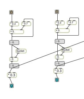
 
Figure 1. Detect Speed of x and y position of colour movement modified from detect_Speed.maxpat from Greg Corness.
We modified the detect speed to not send out the exact speed when the participant has hit or is in contact with the balloon. This is because the balloon was moving too fast than it would in the physical reality when force has been applied. We wanted to simulate drag force and give our balloon some weight by only using 30% of the speed which the participant hits the balloon at. The last object contains a multiplication object that multiplies the incoming speed by 0.30. Essentially, the concept and algorithm behind this implementation is:

 F = ma


(2)  Hitting the Balloon to hard - If the participant hits the balloon to hard, the balloon would pop. There were two factors that caused the balloon to pop. If collision has occurred (participant has hit the balloon) and if the speed of collision is too hard. We simulated the balloon popping by making the image of the balloon disappear for 2 seconds before returning back on screen.

Figure 2. Detect Collision when colour overlaps the balloon image modified from [bounce].maxpat from Greg Corness.
The first step is to detect if a collision has occurred. If a collision has occurred send a signal. This signal is sent out to outlet 2.

Figure 3. Detect Speed of collision modified from detect_Speed.maxpat from Greg Corness.

The second step is to detect the speed when there is a collision. The collision signal is sent from the [bounce].maxpat and when the detect_Speed.maxpat receives it, this patch stores the speed of the x and y of the colour movement at the point of collision. Then, it averages the speed and sends this speed out through outlet 3.

Figure 4. Displaying the balloon off screen modified from [movingDigitalobject1].maxpat from Greg Corness. 

The third step involves checking if the participant has hit the balloon too hard. This was simulated by creating an if statement and hard coding a value indicating a hard (very fast) speed  that would result in the balloon popping and going off screen. The if statement checks if the collision speed is greater than the hard coded fast speed, then sends a signal to a switch object to stop displaying the balloon image. However, we wanted the balloon to appear again so our participant can interact with the balloon again. We used a delay statement that changes the switch gate and makes the balloon appear again after 2 seconds.

Pseudocode:
  1. If  color track overlaps balloon image then send a collision signal (1 or -1).
  2. If collision signal is true then capture the speed at the point of collision.
  3. Calculate the average x and y colour track speed at the point of collision.
  4.  If speed at the point of collision is greater than a threshold value then send a signal to the switch object.
  5. If the switch object receives a signal send 1 to switch gate to make balloon image disappear.
  6. Wait 2 seconds before switching back to original gate displaying the balloon image on screen again.


Wednesday, February 2, 2011

[Week 5] Sketch 1 Balloon Physics Research

I decided to conduct some research on the behavior and physics of a party balloon that we are trying to simulate for our project. Below is an abstract illustration, I completed on Illustrator, of the physics of a balloon when force is applied.


According to Newton's second law, when force such as hard (strong motion) and soft (weak motion)  is applied to an object, the acceleration will change proportionately. In the case of our balloon passing responsive environment, the harder a participant returns the balloon to the second player, the faster the speed (acceleration) of a balloon will travel. However, the balloon will not travel at the same speed as the speed in which the participant hits the balloon. The reason behind this is because of drag force, an opposing air force that slows down the balloon speed. 

The problem is how would we simulate this physical phenomena in Max 5. Our solution is to track the participant as a blob and through using a boolean expression to find out when our blob has collided with the balloon. In parallel, we are also tracking the speed of the blob. When collision occurs, we would store the speed value at collision and use it in the equation: F = m x a.  A (speed will) be multiplied by m (trial and error number that is greater than 1) to best simulate the mass of a balloon in a virtual environment.  

References